Sunday, December 20, 2015

Programming Arduino Pro Mini (5v) Boards

I received a chance to put my hands on some Arduino Pro mini (5v) boards last Friday. Here's how I programed them using a Arduino Uno board as the programmer. Even though the Pro mini version I used is a 5v version, I noticed that it can be programmed and used with 3.3v supply which is a good thing. The only noticeable change is the lower speed of MCU which is evident when blinking an LED using the board.

(1) Remove ATmega328P MCU from an Arduino Uno board which is supposed to be used as the ISP programmer.

(2) Connect this Aruino Uno board with Arduino Pro Mini board according to the following pin connectivity chart.

Arduino Uno <- - > Arduino Pro mini
Tx    < - ->   Tx
Rx    < - ->    Rx
Reset   < - ->   RST
5v    <- - >    VCC
GND    <- - >    GND

(3) Now connect Arduino Uno board to the computer using USB cable and give permission to the mounted device from /dev directory.

(4) From tools menu in Arduino IDE, select following options.

Board:"Arduino Pro or Pro Mini"
Processor:"Atmega328 (5V, 16MHz)"
Programmer: "Arduino as ISP"

(5) Now, browse for the Blink application from the examples and program it into the Arduino Pro Mini through Arduino Uno board.


Saturday, November 21, 2015

MAC Address Spoofing on Linux

Here's a simple shell script which can be used to change the MAC address of your computer to something else. Open your favorite text editor and enter the following content there. Save the file as change-mac.sh somewhere in your system. Move in to the place where this shell script is saved using a terminal and run it using the command sh change-mac.sh which will ask for the root password. Once you enter it, you are done. Try ifconfig command to check whether your MAC address has changed to what you wanted. Don't forget to replace the interface name (wlan0) and MAC address (xx:xx:xx:xx:xx:xx) according to your requirement in the script.

sudo service network-manager stop
sudo ifconfig wlan0 down
sudo ifconfig wlan0 hw ether xx:xx:xx:xx:xx:xx
sudo ifconfig wlan0 up
sudo service network-manager start


Taking full web page screenshots

When taking a screenshot of a web page, we face the difficulty of how to grab the whole page into a single screen capture. Usually a web page doesn't fit into the size of our computer screen forcing us to take several screenshots while scrolling down. To deal with this requirement, there are various tools and browser plug-ins are available. However, recently I found a very nice way to do it using a built-in functionality of Firefox web browser. May be it is important to mention that I did it on a computer running Ubuntu 14.04 64-bit version.

Here's how we do it.

While we are in the required web page on Firefox web browser, use the key combination Shift+F2 to get a text field at the bottom of Firefox window which is a kind of command line to interact with it. On this text field, type screenshot --fullpage and hit Enter. This action will take a full page screenshot and save it to the Downloads directory. If any unnecessary advertisement or a banner is troubling you, it's better to use some ad blocking plug-in for Firefox first. I use Adblock Plus plug-in.

Sunday, November 15, 2015

Memories From SenSys-2015 Days

Hong-Kong airport during our transit
Last several weeks were a very busy time due to an important event I came through in my life. After getting our RealWSN paper accepted, we had to prepare for the journey to attend to the workshop since I was assigned to present it. The great thing about this is the fact that RealWSN-2015 workshop was co-located with SenSys-2015 conference. Therefore we received the great opportunity to attend to SenSys conference this year which is one of the major academic conferences in wireless sensor networks field. It was like a dream which became true after many years working with wireless sensor networks.

Waiting for the next hop at Hong-Kong
As a part of the preparation for the workshop, I had to work on preparing the slides. As usual, I used Latex beamer package to prepare my slides but, this time I added various extra features to make the slides as more beautiful as possible. Even though I have presented research papers for different audiences so far in my life, I found preparing the presentation for RealWSN-2015 much more challenging. Perhaps, the reason is that the audience in the workshop consist of pioneers and major characters of wireless sensor network domain. From our research group, Dr. Kasun, Mr. Chathura Suduwella and me were the members who planned to attend the conference.

A view near the hotel at night
We flew to South Korea in a Cathay Pacific Airlines aircraft and we had a very long transit at Hong-Kong of about five hours. We utilized that time to improve the slides further. When we reach Incheon airport of South Korea, it was evening and the darkness already arrived. Incheon international airport was not a new place to me since I have been here several times. This time, I arrived here after about more than one year and a half. Things seemed have not changed much since my last departure. We took a taxi from the airport to our hotel, which is located in the middle of the downtown of Seoul city. The journey to the hotel from the airport took almost an hour. We could have traveled in subway which is cheaper but, with our heavy baggages it was not very convenient in this late hours. Nice thing about our hotel is that we were in the walking distance to the conference hotel.

Thiemo and Anna, RealWSN-2015 co-chairs
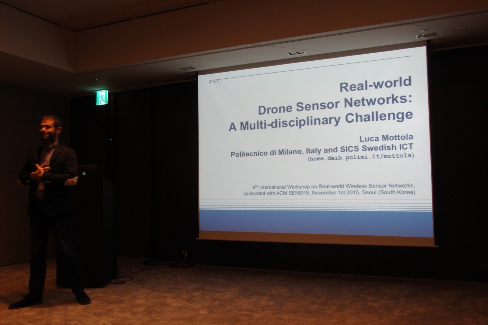
The next day was dedicated to different workshops co-located with SenSys that includes RealWSN where we had to present the paper. According to the workshop program, our paper was scheduled to present after the lunch. First event of the workshop was the keynote speech from Luca Mottola. He talked about drone sensor networks and showed really interesting works, which they have been doing in the recent time. Several people I had came through only in research papers or conference TPC lists were present there. My presentation after the lunch didn't go successfully to the level I expected in my opinion. Anyway, both Dr. Kasun and Thiemo told me that I did a good job.

Luca on his keynote speech
During various breaks we had in the workshop, I managed to talk to several people and get to know them. It was always nice to talk with somebody. A very important part of the workshop was the panel discussion in the evening. Various topics were discussed and among them I noted that people were thinking about the future of wireless sensor network domain. Even though still there are many interesting research problems to solve, it seems like there's no need to have separate conferences dedicated to it. Another interesting topic discussed was how to compare results of papers with one another. The lack of clear benchmarks seems preventing us from properly identifying good results from others.

At the lunch table with some attendees
The day after the RealWSN workshop was the first day of SenSys 2015 conference. Keynote speech of this year was from some guy who was working on self-driving cars. I was not much interested in that topic but it seemed many in the audience were surprised by the results they saw. Since we received the proceedings in a USB drive in the workshop day, we had the chance to read or at least have a glance at every paper while the authors were presenting it at the SenSys stage. It was so exciting to be there among the big people who pioneered wireless sensing world. I found some people who attended to RealWSN in this SenSys main event. Since I didn't know many attendees to SenSys, I tried to be with and talk to those I got to know from RealWSN as much as possible.

Namdaemun gate on my walk way
Next day morning I left Seoul city heading for an important journey alone while Dr. Kasun and Mr. Chathura was at SenSys. I wanted to goto Daegu which is a city located about 237 km away from Seoul. I have many friends including Sri Lankan's and foreigners in Kyungpook National University (KNU) in Daegu. I have been there for a one year which had changed my life in a very important way with so many memories. Since I had several gifts for my friends from home, this visit was so important. From the hotel near the City hall, I walked to Seoul station in the morning to get a train. Morning breeze was so inviting and I didn't feel tired to walk to the Seoul station instead of taking subway.

KTX train at Dong-Daegu station
After reaching Seoul station, I was able to buy a ticket for a KTX train which leave for Daegu so soon. Since I wanted to get there immediately, I decided not to take breakfast from the station and got into the train. I only had a coffee during the journey which was about 1 hour and 55 minutes. KTX climbed upto 300 kmph sometimes on its way and reached Daegu on time. From Dong Daegu station, I walked to the university instead of taking a taxi because I wanted to see around on my way. How many times I have walked between Dong Daegu station and KNU through this way, I wondered. So many memories came into my mind.
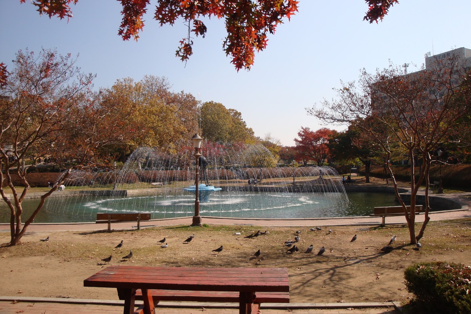
Fountain in KNU
After reaching KNU, I walked all around and met many friends. Since it was a working day, many were so busy and they had to come out of their research labs for a little while to meet me and exchange few words. I handed over the parcels I carried for them which are mostly food items from home. While walking here and there inside the university, I came around various places where I have interesting memories including the fountain. Since it is the Autumn, color of tree leaves have changed from green to yellow and brown. It's not very cold yet so it is convenient to walk and sit outside.

Lunch with Irina, a good friend in KNU
Even though I had a plan to get back to Seoul by lunch time, I realized that it is not possible with this tight time line. One of my good friends in KNU invited me to have lunch together. I was supposed to decide where we would go, so I picked Bingo Pizza which is one of my favorite places in my KNU days. It's a very small place where only about three tables available. They serve pizza in various flavors. I remember visiting this place to have pizza with my fiancée those days. Since now she is back in Sri Lanka, I wished we were both there at this moment. After the lunch I walked to a small department store near KNU to buy little items to bring home. Everything seemed almost the same since I left there one and a half years ago. Finally, I took a taxi to get to the Dong-Daegu station from where I took a KTX train again back to Seoul.

Wan Du won best paper award in Sensys'15
Last day of SenSys conference was an important time since the networking session was scheduled to that day. Many people I have came across while reading research papers were presenting papers there. Thiemo was sitting with his students and colleagues such as Simon Duquennoy, Ambuj Varshney, Wen Hu and Luca Mottola. During the sessions, I received the opportunity to ask few questions from the presenters too. This year, the best paper went to a guy from NTU, Singapore called Wan Du, who presented the paper titled "When Pipelines Meet Fountain: Fast Data Dissemination in Wireless Sensor Networks".

A Korean meal for dinner
After the end of conference, we had a little time to move around since the next day morning we had to go to the airport. So, we traveled around the city in subway during the whole evening and visited various places. During the few days we stayed in Korea, we couldn't try a real Korean food since mostly we ate burgers, Pizzas and other western foods like that. So, to get the final dinner in Korea, we entered a small Korean food restaurant on our way and ordered something. Even though I could read some of the Korean names in the menu, I couldn't exactly understand what each food item was. With the help of the pictures shown in menu, finally we were able to order something. This meal included some kind of Korean soup, rice, beef and some vegetables with Kimchi. It was so tasty and my colleagues were so glad that they finally had a real Korean food.

Thiemo with the interns of SCoRe lab
The next day we returned to Sri Lanka after attending one of the most important conferences in wireless sensor network domain. When I arrive to my living place in Colombo, it was early morning. However, there was no enough time to take a break next day. I had a nap for few hours and then got dressed to visit our lab since Thiemo came to Sri Lanka on the same day on his way back to Sweden. Our interns in SCoRe lab had given him a warm welcome which made him so happy. He mentioned several times that he never expected a treatment like that from our lab.

Thiemo delivering his talk
Thiemo stayed here for few days and discussed about the progress of our research works, the future steps we should take in collaboration, etc. He delivered a nice guest talk for the public audience about the recent advancements in wireless sensor networks. Members of our research group and some undergraduate students were present there. We joined with him for lunches and dinners during the few days he stayed with us. While Thiemo Voigt is a big character in wireless sensor network world who have placed his name in the top, he has a very nice personality to get along with people and have a chat. It was so great to have him here in our research lab at least for few days.

Attending to SenSys conference was a kind of dream come true for me. I was lucky to be there and see how things happen in a top tier conference. However, this should be just the beginning. I'm so determined to make better research results and attend top tier destinations to present my work in the future.

~******~

Friday, November 6, 2015

Our Poster in IEEE MASS 2015

We had a poster in IEEE MASS 2015 conference which was held in Dallas, USA in last month. Even though we couldn't attend to it, we received a generous support from Kasun Hewage who was a colleague in our research group few years back. He was attending to it to present his own paper, so he agreed to represent the poster and set it up there in the conference. He sent few photos of the poster while he was there. I used Scribus tool to prepare the poster which is not something I'm very familiar. However, it seems like the poster looked much better than I thought.

Our poster with it's colleagues.

It looked better than I thought.

Sunday, October 25, 2015

3D Printer in SCoRe Lab

Few weeks ago we received a 3D printer to our research group as a generous donation from our past colleagues. It's model is Prusa i3 Plus 2.85 mm kit. Our guys in the lab used it to print various things starting from simple 3D texts to IC bases. Here are some pictures of it printing our UCSC logo.

Tuesday, October 20, 2015

Programming ESP8266-ESP07 modules

ESP8266-ESP07 module on the breadboard
We recently bought few of the cheap ESP8266-ESP07 modules from the market and wanted to try them. Initially, we had a huge challenge trying to understand how to program them following different tutorial and resources. Somehow finally we found the way. Since this is a completely new thing for many people, I decided to write the steps clearly for everybody's purpose. Here we go.

(1) Download and install Arduino 1.6.5 version (go to build directory and type 'ant run').

(2) Start the Arduino IDE and then open the preferences menu. There's a text field for Additional Board Manager. Enter the following string in this field.


(3) Now open the Board Manager from Tools->Board menu, search for esp8266 platform and install it.

(4) Now, go to the Tools->Board menu and select "Generic ESP8266 Module". Settings related to this board from the Tools menu should be configured as follows.

Flash Frequency: 40MHz
CPU Frequency: 80MHz
Upload Using: Serial
Upload Speed: 115200
Flash Mode: QIO
Flash Size: 1M (512K SPIFFS)

Now our Arduino IDE is ready.

(5) Connect the ESP8266-ESP07 module with the USB-FDTI module as shown below.


ESP8266-ESP07 FDTI programmer
Tx Rx
Rx Tx
GND GND
GPIO15 GND
GPIO0 GND
VCC 5V *
CH_PD (EN) 5V *


* = connect two diodes to drop the voltage to 3.3v

(6) Connect the USB-FDTI module to a USB port of the PC where we run the Arduino IDE. From File menu go to Examples->ESP8266WiFi->WiFiAccessPoint sketch. Change the access point name given in the code to whatever we want.

Now, we can directory program it to the ESP8266 module but before clicking the Upload button of the Arduino IDE, disconnect the VCC supply from the module and connect again. Then only we can program it. Otherwise, it will throw an error. While the code is uploading, blue LED of the ESP8266 module will blink.

(7) After the code is completed uploading, remove the GPIO0 pin from the GND connection. Then disconnect and reconnect the VCC of ESP8266-ESP07 from the FDTI VCC supply. Now, we can check whether the access point is up and running.

Open a Linux terminal and issue the following command which will list the ESSIDs of the access points in the vicinity together with their signal strengths.

sudo iwlist wlan0 scanning | grep -e "ESSID:" -e "Signal level"

In this list, we should be able to see our new access point created by the ESP8266 module.

(8) If we get connected to this access point using the correct password, then we can open a web browser and enter the IP address http://192.168.4.1/ in the address bar. It should return a HTTP response saying "You are connected".

References:


Sunday, September 20, 2015

Debugging Digital Circuits with a Logic Analyzer

While working with digital systems of various kinds, sometimes we face unexpected behaviors from those tiny embedded platforms. Sometimes it can be a hardware defect and sometimes it's just a bug in our code that runs on those systems. Unlike other platforms such as personal computers and smartphones, debugging these embedded systems is very hard and complicated. In this domain, one important tool that helps the developers to look in to the lower level functionalities of a digital circuit is a logic analyzer.

In our lab, we had a very nice logic analyzer tool donated to us by a past colleague who worked here. The tool is Logic manufactured by Saleae. Today I put my hands on it and tried some simple things to get familiarized with the device. First I programmed an Arduino Uno board to blink its on-board LED connected to the pin 13. Then I connected the Logic to the Arduino board. Ground pin of Logic was connected to a Ground pin of Arduino board. Then, pin 1 of the Logic is connected to the Arduino pin 13 using a jumper wire.

Go over to the download page of the Saleae website and download the required software. In my case, I downloaded version 1.1.15 for Ubuntu 12.04. Simply uncompress the ZIP file and there we have an executable file. I ran it from a terminal by issuing the command sudo ./Logic and the software started up. Connect the Logic device to to the computer using the USB cable and then simply clicking on the Start button will capture the data. Having a 1000 millisecond delay between the turning on and off of the LED, I was able to see the output from the software interface as shown below.

Arduino Uno pin 13 switching with 1000 ms delays

Timing seems very precise. Once the pin 13 became high, it took about 1000.872 milliseconds before it switch back to low. In our program code, the delay was set as 1000 milliseconds. As the second test, I removed the delays placed in the code, That means our LED is turning on and off as faster as the AVR microcontroller can perform. Our logic analyzer says that pin 13 stays about 4 microseconds in high state before it return to low.

Arduino Uno pin 13 switching without explicitly placed delays

I think this device will help me in my future endeavors with digital circuits. Let's see what it will bring to me.

Reference:
[1] https://www.saleae.com/
[2] https://www.youtube.com/watch?v=7OCPWCdg2ys


Monday, September 7, 2015

FM Radio Broadcasting with HackRF and GNURadio

Here's a flow graph which can be used for broadcasting some content of a Wav  file over FM radio frequencies. The original flow graph is from here but it created a lot of missing block errors. So I had to edit it a little bit to make something my own which can be downloaded from here. Since it requires a Wav file, I generated it from a MP3 song file using a tool called Sox as follows.

sudo apt-get install sox

sudo apt-get install libsox-fmt-mp3

sox phillip-phillips-home.mp3 -b 16 phillip-phillips-home.wav

Here's how the flow graph looks in GNURadio Companion tool.


GQRX for Quick SDR Jobs

While GNURadio provides very sophisticated capabilities to implement transmitters and receivers using SDR hardware platforms, it is not necessary to create flow graphs and run them in order to view the radio spectrum. For any quick and dirty requirement to view the spectrum, the easiest way is to use GQRX, which is a receiver program based on GNURadio.

Here's some screenshots of GQRX tuned to various frequencies.


Jamming WiFi Channels with HackRF

We can easily capture signals going in a particular frequency using HackRF and also we can retransmit those data back to the air from the file. Here's how we use it to jam some wifi channels. To try this, first I checked what is the specific frequency channel, which is used by my laptop and the WiFi hotspot to communicated. We can find it out by using the following command.

iwlist wlan0 channel

It should list down all the available WiFi channels and at the end, the channel currently we are using. In my case, it was  channel 11 which operated in 2.462 GHz. Now it's time to try jamming. First we should record some data to a file. We can do it with the following command. The parameter -f specify the frequency we need to tune in to in Hz. Similarly the parameter -s specify the sampling rate which I have set to 20 MHz. Finally the parameter -l specify the LNA gain. Reading man files will provide more information about those stuff.

hackrf_transfer -r test.bin -f 2462000000 -s 20000000 -l 40

This command will run for a while and save data to the file test.bin and stop at some point. Still, the reason to stop in that way is mysterious to me. Anyway, now we have some captured data. We can transmit it back. Before doing so, open a new terminal and ping to some public IP address such as 8.8.8.8 so that we can continuously see the ICMP packets going and coming with round trip information. While having the ping command running in that terminal, run the following command from our original terminal. That -x parameter sets the Tx VGA gain.

hackrf_transfer -t test.bin -f 2462000000 -s 20000000 -x 47

During the time period of above transmission going on, we can see that the ping packets are getting disturbed. Either they take a longer round trip delay or completely become unable to be delivered.

Here's a reference I used,


Saturday, August 29, 2015

Processing data out of GNURadio

While working on software defined radio (SDR), I have always worked on GNURadio software which provide a graphical interface. I have to drag and drop various blocks to create flow graphs which perform the functionality I need. It's time to escape the barriers of GNURadio and do further thing out of it. Finally I found the way to do it. We can start with GNURadio flow graphs and transfer data from it to our own python scripts where we have the freedom to do whatever we want with our program codes. I found some good resources from where I learnt it and those things are mentioned under the references section.

First of all to try these things, we need to have installed some software. GNURadio should be there as obvious. Additionally we need a python plotting library which we will be using. Install it as follows.

sudo apt-get install python-matplotlib

Let's clearly understand what we are going to do now. When we run a flow graph created using GNURadio, it will acquire the data from wherever we specified and will process it inside. Resulting data can be visualized as different plots provided as blocks within the flow graph or sometimes we can save data in to a file. Every kind of processing I have done so far are within the flow graph. Now, what we are going to achieve is creating a flow graph which has some special blocks. Instead of running the flow graph straightforwardly, we just generate a python script using GNURadio that represent the flow graph. Then we write a our own python program which will use that GNURadio generated python script as a module to acquire data and then do further processing of data inside our own python script.

It's time for action. Open gnuradio-companion tool and create the following flow graph. It will acquire data from a HackRF device and apply a fast fourier transform (FFT) operation on the data stream. Finally it turns that FFT data in to message block which are ready to be sent out of the flow graph though a special block. I saved this flow graph as fft_data.grc and clicked on the 'generate flow graph' button to generate the python script which implements this flow graph is code. It generates the script called top_block.py automatically.


Once this is done,  we have a python script which will acquire data and provide us FFT data. Let's use it in a our own python script. For this purpose, create a new python program with the name fft_plotter.py and add the content shown below. It should be understandable that we have two functions there. First one draws the FFT for the considered frequencies while the second one draws the variation of signal power of a particular frequency over time. Depending on what we want to plot, we can uncomment the relevant line.


 1
 2
 3
 4
 5
 6
 7
 8
 9
10
11
12
13
14
15
16
17
18
19
20
21
22
23
24
25
26
27
28
29
30
31
32
33
34
35
36
37
38
39
40
41
42
43
44
45
46
47
48
49
50
51
52
53
54
55
56
57
58
59
60
61
62
import grcconvert
import struct
grcconvert.main("top_block.py")
import top_block
import matplotlib.pyplot as plot
import os
from collections import deque

def plot_fft(with_this):

 #Asanka: trying to play with this
 os.system('clear')
 print "------------------------------"
 print "length       =", len(with_this)
 print "start point  =", with_this[0][0], "dB"
 print "center point =", with_this[len(with_this)/2][0], "dB"
 print "end point    =", with_this[len(with_this)-1][0], "dB"
 print "------------------------------"

 plot.clf()
 # it seems logpwrfft exchanges the first and second part of the FFT output, we correct it:
 plot.plot(with_this[len(with_this)/2:]+with_this[:len(with_this)/2]) 
 plot.draw()

def plot_power(data_array):

 os.system('clear')
 print '\n\n'
 print "signal strengh at the center:", data_array[len(data_array)/2][0],"dB"
 
 a1.appendleft(data_array[len(data_array)/2][0])
 datatoplot = a1.pop()
 line.set_ydata(a1)
 plot.draw()
 plot.pause(0.00001)


plot.ion()
tb=top_block.top_block()
tb.start()

#Asanka: experiment
a1 = deque([0]*100)
ax = plot.axes(xlim=(0, 100), ylim=(-100, 0))
ax.grid(True)
line, = plot.plot(a1)
plot.ylim([-150,0])
plot.show()

while True:
 fft=tb.msgq_out.delete_head().to_string() # this indeed blocks
 floats=[] 
 for i in range(0,len(fft),4):
  floats.append(struct.unpack_from('f',fft[i:i+4]))
 print "got",len(floats), "floats; FFT size is", tb.fft_size
 i=0
 while i<len(floats): # gnuradio might sometimes send multiple vectors at once
  pack=floats[i:i+tb.fft_size-1]
  #plot_fft(pack)
  plot_power(pack)
  i+=tb.fft_size
  

This python script and the gnuradio-companion generated python script should be there in the same directory. Finally we need one more python script before we can try running this code. It can be obtained from here and saved into the same directory. It's written by Andras Retzler and I got the code from an example he provided in github.

Now I think we are good to go. Connect HackRF device into a USB port of the computer and run our python script with root privileges.

sudo python fft_plotter.py

Depending on the function we call within our script (we cannot call both at the same time), we will be able to see two different plots as follows.


That's it for the moment!

References:


Thursday, July 23, 2015

Low Frequencies and Solder Fumes

Somewhere inside UoC
Photo credit: Chathura Suduwella
Due to the nature of our research works, it's not enough just to sit in front of a computer and write programs that do certain things. Our work makes us to sniff solder fumes most of the times and sometimes it makes us to move out of the lab and walk all over the university. Last few weeks were so much stressful due to various challenging tasks we were facing. It's not easy but I think I learned so much interesting new things during these hard times. Among various things I was facing, two notable experiences are worth reporting for my future reference.

As a further step of our elephant infrasonic research, our guys wanted to do several field experiments within the university premises. It requires them to take the infrasonic emitter and detector equipment and move all over the university premises which is not as easy as it sounds. While moving we have to take data samples from the infrasonic detector at various places and we need to take note of the GPS coordinates of the particular location. Sometimes our infrasonic emitter stops functioning or gets stuck and sometimes our equipment runs out of battery power. Facing all those troubles, we have to keep moving all over. Joining with Chathura aiya, Poshitha and Waruna, I had a nice time in the field missing the lunch and a work day. Besides the troubles of experiments, we were happy about the outcomes of it.

First three units out of the production line :)
Second move is from the hardware side. Moving ahead of breadboards, we finally managed to
implement a much more usable wireless mote. It has extension headers to connect a USB ASP programmer board to reprogram the MCU without removing it from the mote as it was a very troublesome thing in our earlier version. First I tried everything on a breadboard and then started moving things into the permanent mote. Chathura aiya provided a great assistance in this effort and his confidence and ideas helped so much. Without his guidance, these little things will not be as beautiful and handy as they are at the moment. He exactly knows how to put things in the right position in order to make it smaller and look good.

A lot more interesting work is going on these days. I will try to write a brief note if I found anything worth telling to my future self. For the moment, this is it.


Sunday, July 19, 2015

Serial communication between Arduino and Android

I wanted to establish communication between an Arduino Uno board and an Android device for a project work. Initially I tried usb-serial-for-android library and reached to some level. I was able to read some amount of bytes from the Arduino board. However due to some reason, my Android device disconnects from the Arduno serial connection after a while. In order to try that, I followed the steps mentioned here. It's sad that I spent a whole day trying to make it work but finally failed. Perhaps this library actually works but due to some mistake I made, it's still not ready to work. Anyway, I'm leaving it to try later some other day if I find time.

It took me some time to realize that there are other libraries available to achieve the same thing. Since I ran out of time, I didn't get a chance to try them from scratch but I decided to try some sample apps they provide. These guys in Physicaloid provides an interesting library and sample projects which actually worked for me. Their PhysicaloidLibrary includes sample project in this place and some of those are in google play already.

I installed their USB Serial Monitor Lite app in google play into my Galaxy S3 device which runs Android 4.4.4. Then I installed following simple Arduino sketch into an Arduino Uno board. Connecting the two devices with the help of a USB OTG cable showed me that Arduino board responds to the messages from Android phone by blinking the LED at pin 13 and also by sending reply data.


 1
 2
 3
 4
 5
 6
 7
 8
 9
10
11
12
13
14
15
16
17
18
19
20
21
22
23
24
25
26
27
28
29
30
static int counter = 0;
int led = 13;

void setup() {
        Serial.begin(115200);
        pinMode(led, OUTPUT);     
}

void loop() {
  
  digitalWrite(led, LOW);

  if (Serial.peek() != -1) {
          
          digitalWrite(led, HIGH);
        
        do {
                byte message = (byte) Serial.read();
                //Serial.print("Received: ");
                
                if(message == (byte) '1'){
                        Serial.println("1");
                } else {
                        Serial.println("-");
                }                                                         
        } while (Serial.peek() != -1);     
        
  }
  delay(1000);
}


I think I should look into the source code of this app which can be found here in order to adapt it into my work requirements.

Monday, July 6, 2015

Install GNURadio on Ubuntu 12.04 using install script

When using HackRF device, it is necessary to have GNURadio installed and running in our machine. Until today, what I used was a USB drive installed with a live linux image. This live linux image was pre-configured with GNURadio and other relevant tools. I have written a separate article about GNURadio based on this live linux image. This time, I'm installing GNURadio and relevant tools on my Ubuntu 12.04 system which will save me from requiring to restart the computer to go for a live linux image whenever I have to use HackRF.

Since the installation of GNURadio from source files is a big hassle, I found a wonderful installation script extremely helpful. GNURadio website has indicated it as a good way to install GNURadio and therefore, I decided to go with it. Here's the steps I followed to perform the installation using that script.

(1) Create a folder named 'src' somewhere in the home directory and move into it using terminal

mkdir src
cd src/

(2) Run the following command

wget http://www.sbrac.org/files/build-gnuradio && chmod a+x ./build-gnuradio && ./build-gnuradio

It takes a very long time to download source files and packages, compile them and configure all the necessary things.

(3) Add the following line to the ".bachrc" file in your home directory. This information was printed on the screen during the installation process of the previous step. That's why I followed it to set this path.

export PYTHONPATH=/usr/local/lib/python2.7/dist-packages

(4) Now plug-in HackRF device into a USB port and run following command.

sudo hackrf_info

An output much similar to the following should appear in the terminal then.

Found HackRF board 0:
Board ID Number: 2 (HackRF One)
Firmware Version: 2014.08.1
Part ID Number: 0xa000cb3c 0x00544f46
Serial Number: 0x00000000 0x00000000 0x14d463dc 0x2f6662e1

(5) Now we can start gnuradio companion (GRC) in order to try hackrf device using the following command.

sudo gnuradio-companion

That's it. After the GRC windowed showed up, we can start creating different flow graphs and run them with HackRF device.

Reference:

Tuesday, June 16, 2015

Programming ATtiny85 MCUs using Usbasp programmer on Linux

Usbasp programmer
Until recently, whenever I wanted to program an ATtiny85 chip, I used Arduino as ISP option about which I wrote in an earlier blog post. However, that is not a very convenient way of programming these tiny chips. Because of that, today I'm writing down the steps I followed to try programming ATtiny85 chips using a Usbasp programmer board. We can easily buy them for a very cheap price and no need of a huge effort to set it up for the programming job. In this post I will be doing everything on an Ubuntu 12.04 machine and will use Arduino IDE for the coding. I'm using a USBASP V2.0 board. I will list down the steps I used one by one. So, here we go.

(1) Connect the Usbasp programmer with ATtiny85 chip as shown in the picture. I will be using  a breadboard and few jumper wires for this connection.

Pin connections between Usbasp and ATtiny85
(2) Create a something.rules file in /etc/udev/rules.d. Add the following line into it.

SUBSYSTEMS=="usb", ATTRS{idVendor}=="16c0", ATTRS{idProduct}=="05dc", GROUP="users", MODE="0666"

(3) Now issue the command,

sudo service udev restart

(4) Now Arduino IDE can detect the USBASP programmer when it is connected to the USB port. From the tools menu, select the programmer Usbasp. From tools menu, select the board, "ATtiny85(internal 1MHz clock)".

(5) Program code for the blink program.


 1
 2
 3
 4
 5
 6
 7
 8
 9
10
11
12
13
14
15
16
17
18
19
/*
  Blink
  Turns on an LED on for one second, then off for one second, repeatedly.
 
  This example code is in the public domain.
 */
 
void setup() {                
  // initialize the digital pin as an output.
  // Pin 0 has an LED connected on most Arduino boards:
  pinMode(0, OUTPUT);     
}

void loop() {
  digitalWrite(0, HIGH);   // set the LED on
  delay(1000);              // wait for a second
  digitalWrite(0, LOW);    // set the LED off
  delay(1000);              // wait for a   
}

There will be a warning saying that, 'avrdude: warning: cannot set sck period. please check for usbasp firmware update'. We can simply ignore it.

(6) Now we can connect a LED in between ground and physical pin number 5
of the ATtiny85 chip will cause the LED to blick. In our program code in Arduino IDE, we mentioned the pin as 0 which actually represent the PB0 pin in the ATtiny85 chip. The PB0 pin is actually the physical pin 5.

ATtiny85 blinking a LED
References:

Tuesday, June 2, 2015

Audio Signals in GNURadio

Figure - 1
This time, I'm writing a very little note on how to handle audio signals using GNURadio. There are two basic things we can do. Firstly, we can take audio signals from a microphone in our computer and then visualizing it with various plot. Secondly, we can generate some signal within the audible frequency range and put it out using the speakers of our computer. In between those two options, we have the opportunity to manipulate signals and do whatever the processing we need to perform. Let's begin.

Figure - 2
Prepare a flow graph in GNURadio Companion (GRC) as shown in figure-1 where we just have two components, an Audio Source and a WX GUI Waterfall Sink. These two blocks together will extract the sounds from our computers microphone and show it as in a spectrogram. In is important to understand that we have set the sample rate to 48kHz which is the most commonly supported sample rate in audio devices in our computers. A configuration file for this flow graph setting can be found here. Running this flow graph will result in a beautiful spectrogram as shown in figure-2.

Figure - 3
Similarly, generating an audible sound and sending it to the speaker is also very easy. As shown in the flow graph of figure-3, we mainly need two components, a Signal Source and an Audio Sink. Our signal source generate signals in the sample rate of 48kHz as in the previous case. Instead of setting a predefined frequency for the signal source, we have added a WX GUI Slider which defines the frequency of the signal source. The configuration for this flow graph can be found here. Running this flow graph results in a tone which changes it's pitch as we move the slider to adjust the frequency. It is notable that when we increase the frequency beyond 20kHz, the sound goes out of our hearing as our ear is not sensitive to frequencies out of that boundary.